DIAGNOSTIC RESPONSE:
Maintain range selected, observe gear shift direction circuit
CIRCUIT DESCRIPTION:
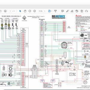
The OEM 4th Generation Controls shift selectors communicate with the Transmission Control Module (TCM) by exchanging standardized digital messages over the SAE J1939 Controller Area Network (CAN). The physical network consists of a two-wire twisted-pair harness and, typically a third shield wire. A single 120 Ω termination resistor is located at each end of the network and produces 60 Ω resistance for the circuit. Vehicle OEMs may choose to install external termination resistors or use internal termination resistors built into many SAE J1939 electronic modules, including the TCM and shift selector. This DTC test verifies that there is SAE J1939 communication between the TCM and the primary SAE J1939 shift selector by monitoring a State of Health (SOH) message. This DTC is active when the SOH message is lost. Refer to the OEM Technician’s Library for additional information.
CONDITIONS FOR RUNNING THE DTC:
After TCM initializes normally and engine speed is above 200 rpm for more than 5 seconds.
CONDITIONS FOR SETTING THE DTC:
DTC U0103 sets when:
1. The TCM has not received a SAE J1939 SOH message from the active primary shift selector for 4 seconds.
2. The TCM has not received a SAE J1939 SOH message from an inactive primary shift selector for 8 seconds (for dual shift selector applications).
3. The shift selector is not strip shift selector.
NOTE: The primary shift selector is also referred to as Gear Shift Module 1 (Shift Selector).
ACTION TAKEN WHEN THE DTC SETS:
When DTC U0103 is active, the following conditions occur:
1. The DTC is stored in the TCM history.
2. The TCM illuminates the CHECK TRANS light.
3. The TCM upshifts and downshifts according to the PWM signal (W134) from shift selector.
4. If the shift selector has lost communications with the TCM, the TCM commands the last valid selected gear, and any pre-select capability is disabled.
5. When this DTC is active, the shift selector freezes the current display for about 1.5 seconds followed by 10.5 seconds of a blank display. If the shift selector still has power, then dual cat-eye symbols appear in both displays to notify the operator that range monitor and range select data is unavailable to the shift selector.
CONDITIONS FOR CLEARING THE DTC/CHECK TRANS LIGHT:
Use the diagnostic tool to clear the DTC from the TCM history. The TCM automatically clears the DTC from the TCM history if the vehicle completes 40 warm-up cycles without the DTC recurring.
DIAGNOSTIC AIDS:
1. DTC U0103 indicates a missing datalink message for the shift selector SOH message. This DTC may be caused by:
– Miswired or mis-pinned shift selector harness.
– Loss ignition or battery power to primary shift selector.
– Miswired or defective OEM controllers, OEM components, or OEM circuits attached to the
datalink.
– Electrical noise.
– Bus-loading.
– Short to power or short to another wire in datalink wiring.
– High resistance or open in datalink wiring.
– Poor vehicle grounds.
– Unlocked connectors, expanded terminals, poor pin crimps or unlocked pins causing high
resistance or open circuit.
– Unlocked connectors, unlocked pins, causing shorts in connectors.
– TCM ground is at different voltage potential than the ground of the OEM voltage source
responsible for shift selector.
– Defective TCM.
– Defective shift selector.
2. Vehicle manufacturers may use the following terminal pairs for CAN 1 high and low wires:
– Terminals 8 and 28.
– Terminals 48 and 68.
– Both terminals 8 and 28 and terminals 48 and 68 are wired in a pass-through setup.
3. Vehicle manufacturers may wire the TCM into the CAN1 backbone in three different ways:
– The TCM may be on its own stub as in traditional CAN backbones.
– The TCM may be wired in a pass-through configuration so that the CAN high and low wires are
connected to two separate pin pairs in the TCM 80-way connector. Datalink messages pass-
through but can still be viewed by the TCM.
– The TCM may represent one end of the backbone. Typically, the internal resistor in the TCM will
be used in this setup.
4. An active DTC U0103 may prevent the diagnostic tool from communicating with the TCM. The J-47276 TCM Reflash Harness may be used to confirm that the TCM is operational. Connect the TCM Reflash Harness to the TCM and leave the OEM harness disconnected. Provide input power from the J-42455-A Load Box.
5. CAN1 and CAN2 devices must not be interconnected because they are incompatible with each other. CAN1 operates at 250 kbps data rate and CAN2 operates at 500 kbps data rate.
6. For proper datalink communications, it is necessary to have two 120 Ω resistors installed in parallel across the CAN1 High and CAN1 Low terminals. Resistance across CAN1 High and CAN1 Low should measure 60 Ω when wired correctly.
Review applicable information in the OEM Technician’s Library, Control System and Transmission Specifications, and other related information.
Related


![download Hitachi Construction Machinery MPDr Ver 3.7.0.0 [10.2020] Diagnostic Software](https://i0.wp.com/www.ecuforcetruck.com/wp-content/uploads/2023/05/MPDR-3.7.00.png?resize=300%2C300&ssl=1)
![download Hitachi Construction Machinery MPDr Ver 3.7.0.0 [10.2020] Diagnostic Software](https://www.ecuforcetruck.com/wp-content/uploads/2023/05/MPDR.png)