DIAGNOSTIC RESPONSE:
Use default values
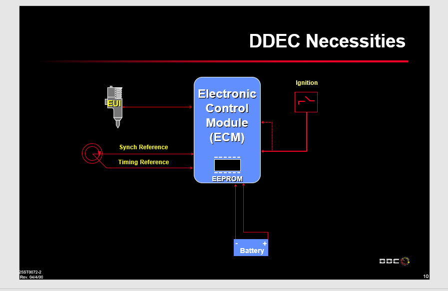
CIRCUIT DESCRIPTION:
In OEM 4th Generation Controls, the preferred digital datalink is the SAE J1939 Controller Area Network (CAN). The Transmission Control Module (TCM) communicates with the engine control module and other controllers by exchanging standardized digital messages over SAE J1939. The physical network consists of a two-wire twisted pair, two 120 Ω termination resistors and, in most cases, a third shield wire. A 120 Ω termination resistor is located at each end of the network. Vehicle OEMs may choose to install external termination resistors or use internal termination resistors built into many SAE J1939 electronic modules, including the TCM and shift selector. Refer to the OEM Technician’s Library for additional information.
CONDITIONS FOR RUNNING THE DTC:
After TCM initializes normally and engine speed is above 200 rpm for more than 5 seconds, this DTC test will run at 0.1 second intervals.
CONDITIONS FOR SETTING THE DTC:
DTC U0115 sets when SAE J1939 engine torque, engine throttle. or engine coolant messages are not received for 5 seconds or more.
ACTION TAKEN WHEN THE DTC SETS:
1. The TCM does not illuminate the CHECK TRANS light.
2. DTC is stored in TCM history.
3. Default values are substituted for missing data, e.g., engine throttle percentage, engine torque, engine coolant temperature.
4. The TCM freezes shift adapts (DNA).
CONDITIONS FOR CLEARING THE DTC/CHECK TRANS LIGHT:
Use the diagnostic tool to clear the DTC from the TCM history. The TCM automatically clears the DTC from the TCM history if the vehicle completes 40 warm-up cycles without the DTC recurring.
DIAGNOSTIC AIDS:
DTC U0115 indicates missing data on CAN1, i.e., either engine throttle, engine torque, or engine coolant temperature. This DTC may be caused by:
1. Engine DTCs. Some manufacturers may delay throttle, torque, or engine coolant temperature messages during their fault pending logic process, which may result in an active DTC U0115 on the transmission side.
2. Miswired or defective OEM controllers, OEM components, or OEM circuits attached to CAN 1. These may include:
– electrical noise.
– bus-loading.
3. Defective TCM.
Vehicle manufacturers may use the following terminal pairs for CAN 1 high and low wires:
1. Terminals 8 and 28.
2. Terminals 48 and 68.
3. Both terminals 8 and 28 and terminals 48 and 68 are wired in a pass-through setup.
Vehicle manufacturers may wire the TCM into the CAN1 backbone in three different ways:
1. The TCM may be on its own stub as in traditional CAN backbones.
2. The TCM may be wired in a pass-through configuration such that the CAN high and low wires are connected to two separate pin pairs in the TCM 80-way connector. Datalink messages pass-through but can still be viewed by the TCM.
3. The TCM may represent one end of the backbone. Typically, the internal resistor in the TCM will be used in this setup.
An active DTC U0115 may prevent the diagnostic tool from communicating with the TCM. The J-47276 TCM Reflash Harness may be used to confirm that the TCM is operational. Connect the TCM Reflash Harness to the TCM and leave the OEM harness disconnected. Provide input power from the J-42455-A Load Box.
CAN1 and CAN2 devices must not be interconnected because they are not compatible with each other. CAN1 operates at 250 kbps data rate and CAN2 operates at 500 kbps data rate.
For proper datalink communications, it is necessary to have two 120 Ω resistors installed in parallel across the CAN1 High and CAN1 Low terminals. Resistance across CAN1 High and CAN1 Low should measure 60 Ω when wired correctly.
Review applicable information in the OEM Technician’s Library, Control System and Transmission Specifications, and other related information.
Related


![DOOSAN DMS-5 3.1.3 [2023.11] diagnostic software](https://i0.wp.com/www.ecuforcetruck.com/wp-content/uploads/2023/11/1.png?resize=300%2C300&ssl=1)
![DOOSAN DMS-5 3.1.3 [2023.11] diagnostic software](https://www.ecuforcetruck.com/wp-content/uploads/2023/11/Captura-1.png)