


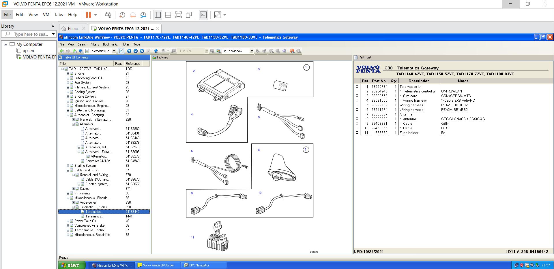
![Volvo Penta EPC 6 Offline VMware [12.2021] VMware](https://i0.wp.com/www.ecuforcetruck.com/wp-content/uploads/2022/11/VOLVO-PENTA-2021-A.jpg?resize=300%2C300&ssl=1)


Related products
-

Bendix ABS EC-30 Fault Code: SID 251 FMI 3
Bendix ABS -

-
-
-
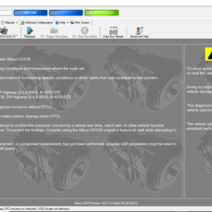
Allison 1000 & 2000 Gen 4 Fault Codes: U1301 J1850 (Class 2) Serial Data Communication Link Low
1000 & 2000 Gen 4 $50.00 -
-
-
-
Allison 1000 & 2000 Gen 4 Fault Codes: P1688 Unmanaged Engine Torque Delivered To TCM Signal
1000 & 2000 Gen 4 $50.00 -
Allison 1000 & 2000 Gen 4 Fault Codes: U1000 Class 2 Loss of Serial Data Communication
1000 & 2000 Gen 4 $50.00 -
-
Allison 1000 & 2000 Gen 4 Fault Codes: U1064 J1850 (Class 2) TBC Controller State of Health Failure
1000 & 2000 Gen 4 $50.00 -
-
Allison 1000 & 2000 Gen 4 Fault Codes: P0123 Pedal Position Sensor Circuit High Voltage
1000 & 2000 Gen 4 $50.00 -

-

-

-

-

-

-

-
Sale!


SERVICE MANUAL 3000 AND 4000 SERIES GEN 4 GENERATION – ALLISON
Allison Original price was: $19.00.$17.00Current price is: $17.00. -

-

-
