CIRCUIT DESCRIPTION:
The speed sensors are variable reluctance devices which convert mechanical motion to an AC voltage. Each sensor consists of a wire coil wrapped around a pole piece that is adjacent to a permanent magnet. These elements are contained in a housing which is mounted adjacent to a rotating ferrous member. Two signal wires extend from one end of the housing and an exposed end of the pole piece is located at the opposite end of the housing. The permanent magnet produces lines of flux around the pole piece. As a ferrous object (such as a gear tooth) approaches and passes through the gap at the end of the pole piece, an AC voltage pulse is induced in the wire coil. The TCM calculates the frequency of these AC pulses and converts it to a speed value. The signal wires from the sensor are formed as twisted pairs to cancel magnetically induced fields. The cable is also shielded to protect from voltage-related fields. Noise from other sources is eliminated by using two-wire differential inputs at the TCM. DTC P0716 can be set when one of the following occur, unrealistic large change in turbine speed, or noisy turbine speed signal.
ACTION TAKEN WHEN THE DTC SETS:
When DTC P0716 is active, the following conditions occur:
1. If failure occurs while in a forward range and a shift has been completed, the transmission will remain in the current range.
2. If failure occurs while in a forward range and a shift is in progress, the transmission will return to the previous range, except in post-shift state; then the transmission will continue to the commanded range.
DTC P0716 is stored in the TCM history.
The CHECK TRANS light illuminates (non-OBD II strategy).
The TCM inhibits TCC engagement.
The TCM forces Variable Modulated Main off.
CONDITIONS FOR CLEARING THE DTC:
The diagnostic tool may be used to clear the DTC from the TCM history. The TCM automatically clears the DTC from the TCM history if the vehicle completes 40 warm-up cycles without the DTC recurring.
DIAGNOSTIC AIDS:
The following procedures are not documented in any OEM procedures or in any OEM Troubleshooting or Service information and therefore should not be used as a method to diagnose any transmission DTCs, function, or shift quality concern:
1. Back-probing any connections used for transmission features or functions may damage and/or unlock terminals from the back-probed connector creating permanent or intermittent shorts and/or open circuits. If possible, use the J-39700 Breakout Box, the appropriate harness adapters, and appropriate magnetic overlays to troubleshoot the vehicle.
2. Load-testing any transmission-related circuits with any other electrical devices such as vehicle lamps or relays, especially with the TCM connected to the harness. Use J-39700 Breakout Box and appropriate harnesses with the diagnostic tool to monitor the circuit performance in question unless otherwise
specified in the various Troubleshooting information.
3. Piercing a wire to check for voltages, shorts-to-grounds or other wires anywhere in the circuit but especially at the TCM. This creates a leak path for moisture and damages the wire and insulation.
Inspect the wiring for poor electrical connections at the TCM. Look for the following conditions:
1. A bent terminal.
2. A backed-out terminal.
3. A damaged terminal.
4. Poor terminal tension.
5. A chafed wire.
6. A broken wire inside the insulation.
When diagnosing for an intermittent short or open, massage the wiring harness while watching the test equipment for a change.
You may have to drive the vehicle in order to experience a fault.
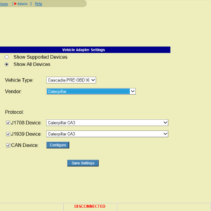
If the condition is intermittent, connect the diagnostic tool and select the speed sensor indicated by the DTC. If the signal is erratic, investigate and eliminate the following:
1. Intermittent wiring connection
2. Excessive vibration (driveline or engine torsional)
3. Irregular sensor gap (loose sensor, loose, or damaged tone wheel)
Install a known good speed sensor and see if normal function is restored to rule out an internal short or open in the sensor removed.
Check that the speed sensor wiring consists of twisted pairs at the rate of 12 to 16 twists per 300 mm (12 inches). These twists must extend the entire length of the wiring harness to within at least 50 mm (2 inches) of the speed sensor connector.
Inspect the turbine speed tone wheel/Power Takeoff (PTO) gear for possible damage.
Related