


-

-

-

-


-

-

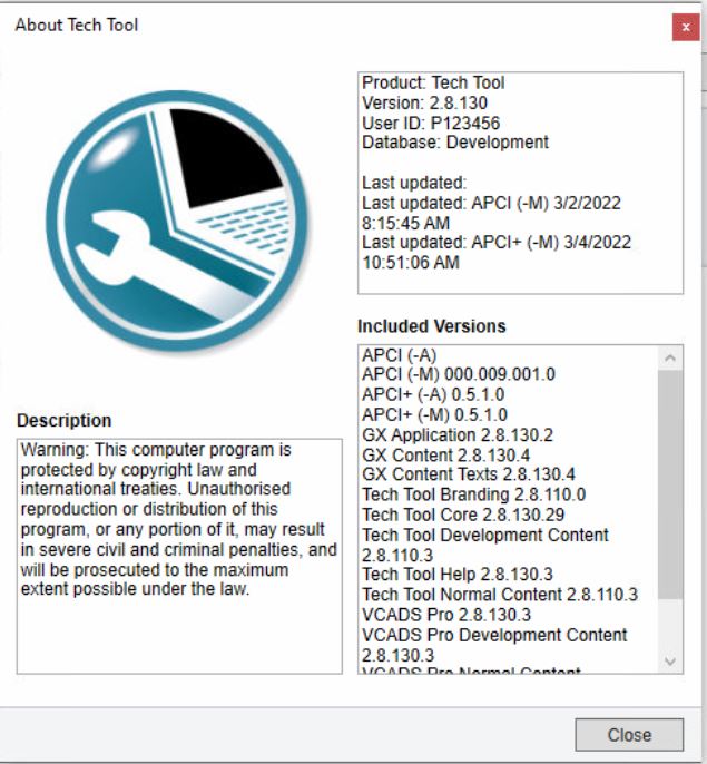
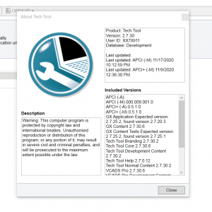
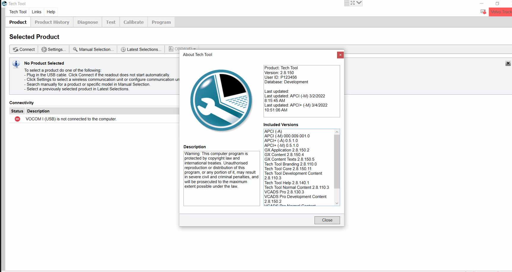
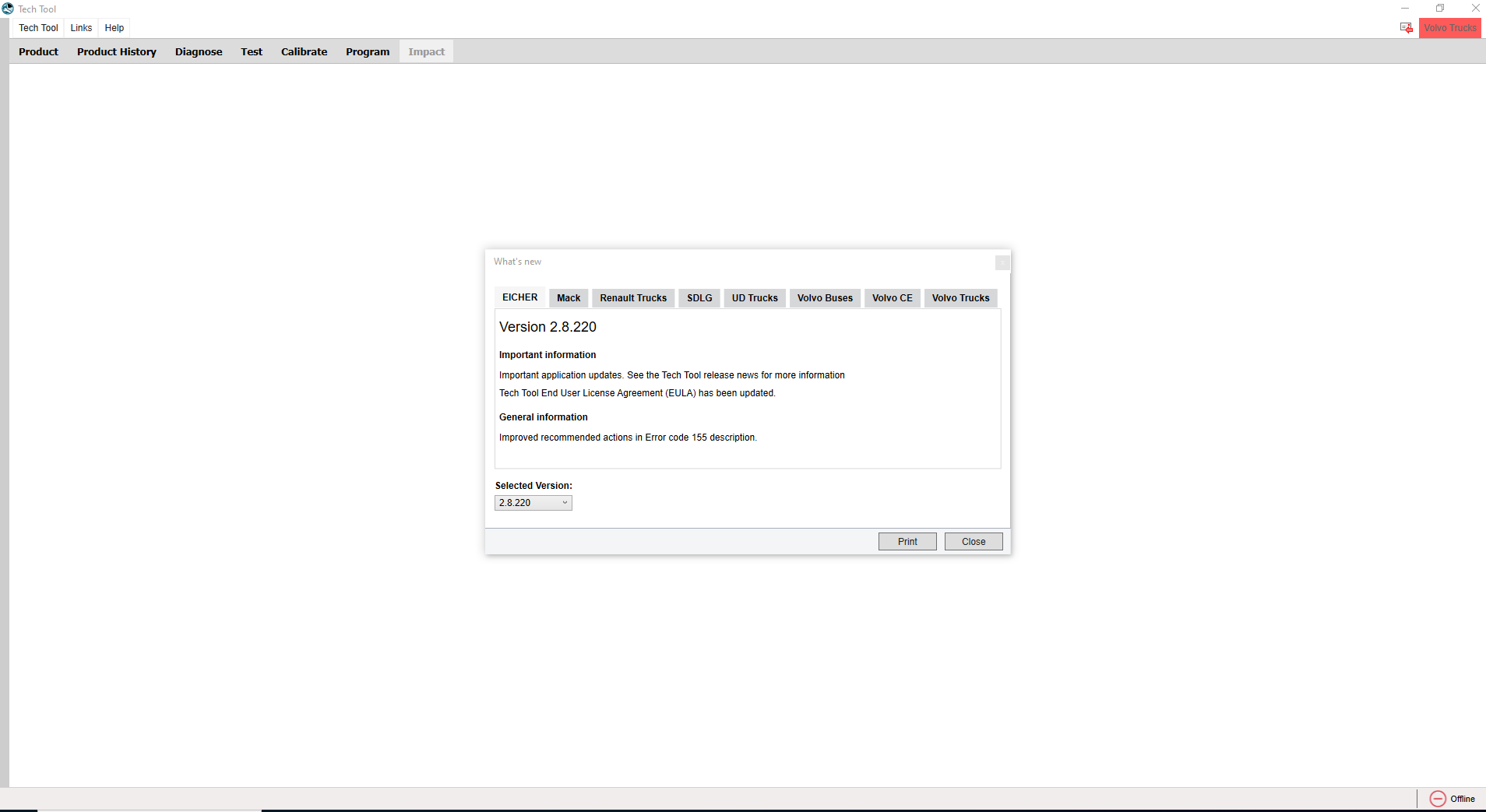
Volvo Premium Tech Tool PTT 2.8.130 Diagnostic Software 04.2022 ACPI ( 1 PC )
Trucks software $143.00 -

-

-

-

-
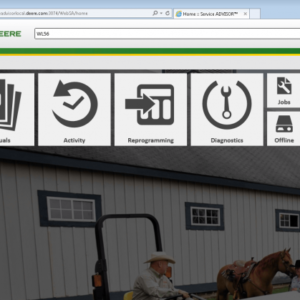
![JOHN DEERE PARTS ADVISOR & HITACHI 2.24.2 [2023.07] - ECUFORCETRUCK EPC](https://i0.wp.com/www.ecuforcetruck.com/wp-content/uploads/2023/09/1.png?resize=300%2C300&ssl=1)
![JOHN DEERE PARTS ADVISOR & HITACHI 2.24.2 [2023.07] - ECUFORCETRUCK EPC](https://www.ecuforcetruck.com/wp-content/uploads/2023/09/2.png)
-

-

-

-

Related products
-

Allison 1000 & 2000 Gen 4 Fault Codes: P2773 Torque Control Request Ignored – ECM/TCM
1000 & 2000 Gen 4 $50.00 -
-
Allison 1000 & 2000 Gen 4 Fault Codes: P0870 Transmission Pressure Switch Solenoid E Circuit
1000 & 2000 Gen 4 $50.00 -
-
Allison 1000 & 2000 Gen 4 Fault Codes: U1064 J1850 (Class 2) TBC Controller State of Health Failure
1000 & 2000 Gen 4 $50.00 -
Allison 1000 & 2000 Gen 4 Fault Codes: U1300 J1850 (Class 2) Serial Data Communication Link Low
1000 & 2000 Gen 4 $50.00 -
Allison 1000 & 2000 Gen 4 Fault Codes: U1000 Class 2 Loss of Serial Data Communication
1000 & 2000 Gen 4 $50.00 -
Allison 1000 & 2000 Gen 4 Fault Codes: P0123 Pedal Position Sensor Circuit High Voltage
1000 & 2000 Gen 4 $50.00 -
-
Allison 1000 & 2000 Gen 4 Fault Codes: P0848 Transmission Pressure Switch Solenoid D Circuit High
1000 & 2000 Gen 4 $50.00 -
Allison 1000 & 2000 Gen 4 Fault Codes: U0032 J1850 (Class 2) Serial Data Communication Link High
1000 & 2000 Gen 4 $50.00 -

-
Allison 1000 & 2000 Gen 4 Fault Codes: P0122 Pedal Position Sensor Circuit Low Voltage
1000 & 2000 Gen 4 $50.00 -
-
Allison 1000 & 2000 Gen 4 Fault Codes: P2771 Four-Wheel Drive Switch Circuit
1000 & 2000 Gen 4 $50.00